Mass Air Flow Meter
A MAF (Mass Air Flow) sensor measures how much air is entering the engine. The engine computer (ECU) uses this information to calculate how much fuel to inject so the air-fuel mixture stays correct. Most MAFs work by sensing how much incoming air cools a heated element, which tells the ECU the mass of the air, not just its volume. The MAF sends a voltage back to the ECU (the raw MAF) which is then converted to an actual MAF value in Kg/h units using a calibration curve.
TunerStudio Setup
By default, most ECUs will be set to run on manifold absolute pressure (MAP) not MAF. Under Base Engine>Base Engine Settings>Fuel strategy, change it to MAF air charge. Under Sensors>MAF Sensor, ensure that the MAF ADC input is set to the correct pin on the ECU (it will likely be labelled as MAF).
Next in the sensors tab, open the MAF Transfer Function setting. This graph represents the corporation between the MAF raw voltage and the actual MAF reading. If data is available for your specific MAF, that can simply be copied across and used (cautiously checking it when driving for the first few times). If MAF data is unavailable, it can be approximated which is detailed below.
Before starting the engine for the first time it is wise to ensure the VE Fuel Table is filled with values of "100", a value of 100 means that the fuel calculation uses 100% of its measured air mass to decide on the fuel injection pulse. Tuning this table will adjust for dynamic airflow effects that happen in the inlet of an engine and will allow small (or large but hopefully not) corrections to the fuel injection which may be required to have the engine meet it's desired air/fuel target. The VE table should only be tuned if the engine is not meeting the desired air/fuel target under relatively steady state conditions (i.e. without any acceleration enrichment or overrun fuel cut). If a different air/fuel ratio is desired at a specific load or RPM then the AFR Table is the correct table to adjust instead.
MAF Transfer Function Approximation
Ideally, connect the MAF to a calibrated air flow bench and collect the transfer function voltage vs Kg/h data that way. Most users however are unlikely to have access to this but luckily the function can be approximated using the data logging features on the car and the following steps:
Preliminary Approximation
-
Ensure the car is set to run on Speed Density in Engine>Base Engine Settings>Fuel strategy (NOT MAF AIR CHARGE) and has a drivable tune to run on the MAP sensor. This means the MAP line needs to be installed. Ideally have DFCO and closed loop fuel correction disabled. Also leave the VE table as set to run on MAP.
-
Connect the MAF sensor and ensure that the MAF ADC input is set to the correct pin on the ECU (it will likely be labelled as MAF). The MAP pin assignment is under Sensors>MAF Sensor.
-
Take the car out for a drive at different engine loads and ensure it is logging data either to the laptop or onboard SD card.
-
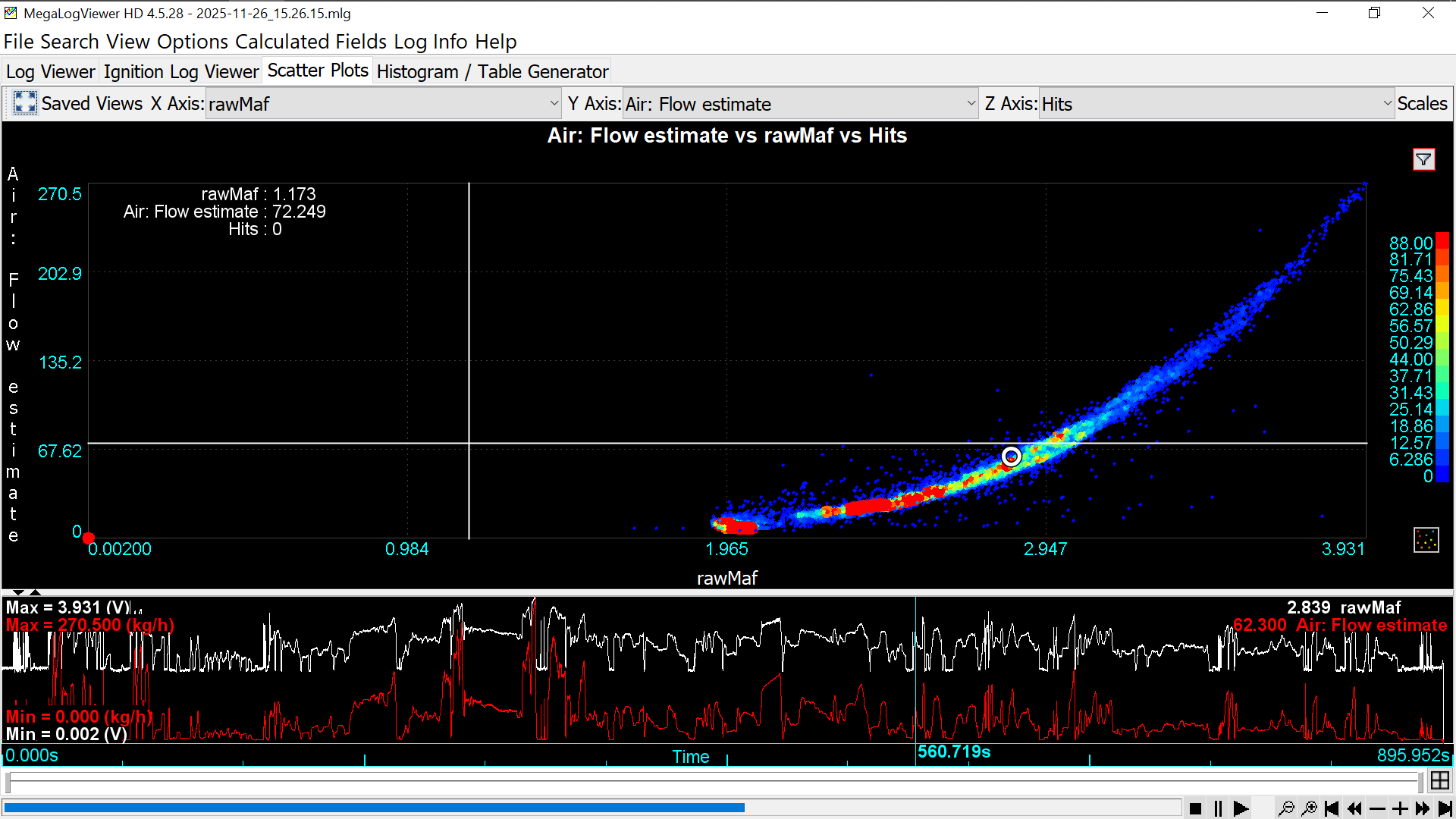
After the drive, open the data log in Mega Log Viewer and under the scatter plots tab, create a plot of rawMaf on the X-axis, Air: Flow Estimate on the Y-axis, and Hits on the Z-axis. This will create a preliminary starting curve to use for calibrating the MAF. This curve is essentially plotting the derived MAF value on the Y-axis using the actual MAP data and other sensors vs the actual MAF sensor voltage.
-
Copy the preliminary curve across to the _MAF transfer function under Sensors. It only needs to be a rough approximation as it will be refined from here.
Refined Approximation
Now using the preliminary curve and the actual MAF readings, the transfer function will be improved.
-
Under Base Engine>Base Engine Settings>Fuel strategy, change it to _MAF air charge. Ensure that DFCO and closed loop fuelling are also off.
-
Save/export your current VE table so as not to loose it if you want to switch back to MAP in the future. Now set all values in the VE table to 100. In the AFR/lambda target table, set all values to 14.7/1.0 respectively.
-
While logging, take the car out for a drive being smooth with the throttle inputs and with a large range of engine loads.
-
Open the log in Mega Log Viewer and load the log. Under Calculated Fields>Custom Fields select Add Custom Field. Name it Target_MAF and use the equation: [MAF]*[Lambda 1]/[Fuel: target lambda]. This equation calculates the corrected MAF value using the actual MAF value and the lambda sensor.
-
Create a scatter plot with rawMaf (volts) on the X-axis, Target_MAF (Kg/h) on the Y-axis, ans Hits on the Z-axis. The scatter plot should hopefully produce a relatively defined transfer function. Open the _MAF transfer function and add the average points of the scatter plot transfer function to it.
-
You should now have a reasonably calibrated MAF sensor. You can now reset the target lambda tables to its previous value and take the car out for a careful drive. The VE table should stay at 100, only changing slightly if the car cannot reach the AFR targets in a specific area. You can use the Tune Analyze Live tool in TS to fully dial in the VE for the MAF as there will likely be some inaccuracies which the VE table will absorb.